výmena vodítok na hlave Ariela
Výmena vodítok na hlave Ariela
Valve guides replacement in Ariel engine head
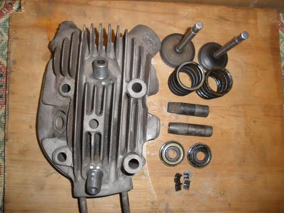
Toto je postup, ktorý som použil pri oprave hlavy válca na Ariel 500 OHV rok 1929.Vodítka ventilov na Mirovom stroji už boli mechanicky poškodené a ventile nemali správny chod. Rozhodol som sa teda pre výmenu. Hlavu som očistil od mastnoty a nečistôt. Rozobral som postupne obidva ventilové zámky a vysunul pružiny. Hlavu som následne opieskoval, čím som z nej odstránil posledné zbytky karbónu a hrdze. Vodítka ventilov som vylisoval za studena. Chcel som použiť čo najviac pôvodných dielov a preto som sa rozhodol ,že ponechám aj pôvodné ventile. Nechal som teda prebrúsiť stopky ventilov, aby som z nich odstránil drobné poškodenia. Spôsobilo mi to však drobný problém, pretože som nedokázal zohnať výstružník na mieru a musel som ho dať prebrúsiť. Na vodítka som použil šedú liatinu legovanú cínom od výrobcu Buzuluk
This is the procedures I did while repair of the 1929 Ariel 500 OHV engine head. The valve guides on Miro´s machine were damaged mechanicaly and the valves did not move properly. I decided to replace them. I cleaned the engine head from all grease and dirt. Step by step I dismantled both valve locks and pushed out the springs. Then I sand blasted the head what removed last remains of carbon and rust. I pressed out the valve guides when cold. I wanted to use as much original parts as possible and so I decided to use the original valves again. I let the valve stems to be sanded to remove small surface damages. But it caused a slight problem because I could not get hold of the correct size drill and I had to have it adjusted. For making the valve guides I used a grey cast iron alloyed with tin from Buzuluk
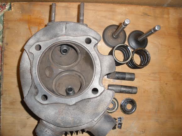
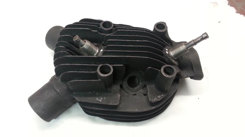
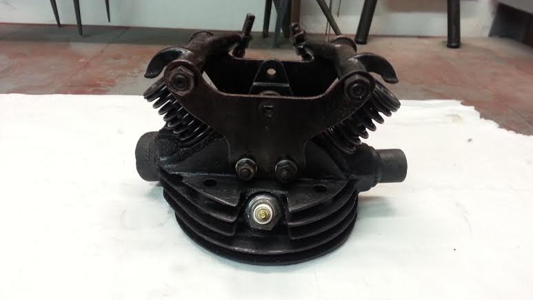
a.s.Komárov. http://www.buzuluk.eu/ Vodítko musí byť vyrobené na jedno upnutie včítane prestruženia otvoru pre ventil. Časť vodítka, ktorá bude v hlave musí byť vyrobená s presahom 0,03-0,05mm. Otvor v hlave pre vodítko je dobré skontrolovať výstružnikom a hlavu je teba nastriekať farbou na vysoké teploty, ešte pred montážou nových vodítok. Ja som na to samozrejme zabudol a tak som musel oblepovať pružiny ventila pri povrchovej úprave. Hlavu som nahrial na elektrickej platničke a vodítka som nechal zmraziť v mrazničke (doporučujem zatajiť pred manželkou). Farba sa pri prvom vypálení poriadne upne na kov. Škoda len, že to na prvý raz trocha zadymí. Rozdiel teplôt spôsobí, že vodítka idú do hlavy ľahkým nabitím plastovým kladivom. Po vychladnutí je ešte treba skontrolovať, či ventil nemá príliš tuhý chod pohybu a v prípade potreby ešte raz prestružiť. Pre úpravu sediel ventilov som som použil 45° kužeľovú frézku. Stopku frézky som však tiež musel nechať prebrúsiť podľa otvoru pre ventil v tolerancii H7. Ventil som ešte zabrúsil najprv hrubou a potom jemnou pastou na ventile, aby dokonale sedel. Pružiny a misky ventilov boli nepoškodené a tak som hlavy zmontoval na komplet. Tesnosť som skontroloval tak ,že som hlavu obrátil a nalial som do nej technický benzín. V prípade prepúšťania je treba proces zabrusovania pastou zopakovať.
production company from Komárov. The guide must be made within one clamping including the hole for the valve. The part of the guide which will be inside of the engine head must be made with 0,03-0,05 mm overlap. The opening in the engine head where the guide will be mounted should be checked with a drill and then the head surface should be treated with a heat resistant pain before the new valve guides are installed. Of course I forgot about it and had to cover the valve springs before the painting. I heated the head on an electric stove and put the valve guides to the freezer (I recommend not to inform your wife about it). The paint sticks securely to the surface after the first heating and smokes a little bit too. The difference in the temperatures will make the valve guides slide into the engine head easier with just light use of plastic hammer. After cooling down it is necessary to check that the valve moves in the guide without sticking and have it turned if needed. For adjustment of the valve seats I used a 45 degree cone cutter. The cutter stem had to be sanded according to the valve opening in a H7 tollerance. I honed the valve using the abbrasive paste to fit perfectly. The springs and valve seats were in a good shape so I could put the engine heads completely. I checked the tightness by turning the engine head upside down and poured technical gasoline inside. In case of leaking the honing process has to be repeated.
Karol Burger
PS. opravovali sme viac kusov hláv, preto nie všetky obrázky sú z jedného motora.
PS. we were repairing more engine heads at time so the photographs are not from just one engine repair.
Translated by Rastislav Chmelár
Komentáre
Pridať komentár